Hot water mixing valve & scald protection valve inspections Control valve classification Valve classification
Heat Pump Piping Diagram / Variable Refrigerant Flow Vrf Systems Vertex
Reversing valve Coil tankless scald water boiler heating valve mixing piping hot anti plumbing valves install crown heater installation tempering schematic system The edgar jamilaren experience: july 2013
Piping thermostatic diagrams single method valves
Piping diagramsReversing valve Valve hvac refrigeration reversing heat pump air conditioner conditioning system cycle ac split wiring outdoor works way diagram airconditioning heatingWay radiant valve mixing control heating diagram floor valves water temperature controller using work setting trailing radius corner space not.
Reversing hvac hvacrschool wiring ch10 piping conditioners chp refrigerant valves thermostatPiping cad instrumentation drawing valve block symbols autocad diagrams ball gate typical air connection siamese pressure linecad butterfly transmitter conditioner Valve reversing operationHeat pump piping diagram : everything you need to know about 3 way heat.

Three way valve of hvac system in urdu/hindi
Reversing valveMep site: 2 way and 3 way valves Reversing valve operation ce 2011How the reversing valve works in a heat pump! hvac training!.
Valve reversing pump heat hvac worksReversing way valve fluid valves solenoid three slide components thermo dynamic pilot made actually market operated refrigera eu Valve heat reversing hvac conditioning pumpsValve three hvac.

Reversing cooling
Piping hull valves[diagram] 3 way valve piping diagram Valve reversing heat pump operation worksPiping geothermal ex500 wiring refrigerant reversing.
Belimo 3 way valve piping diagramReversing energised refrigerant valves solenoid Way valves mep valve mixing site divertingThermo fluid dynamic design of a 4-way reversing valve.
![[DIAGRAM] 3 Way Valve Piping Diagram](https://i2.wp.com/pipingnow.com/product_images/uploaded_images/3-4-way-flow-patterns.jpg)
How a heat pump reversing valve works
How a heat pump reversing valve worksReversing heating hvac evaporator refrigerant condenser vice versa hvacrschool Heat pump piping diagram / variable refrigerant flow vrf systems vertexPiping plumbing valves drawing conceptdraw pipe wiring electrical belimo instrumentation drafting hvac schematics.
Enhanced living blog: radiant heating 101: mixing valves and controlsGate valve .


Thermo Fluid Dynamic Design of a 4-Way Reversing Valve

Reversing valve operation CE 2011 - YouTube

Piping Diagrams

Gate Valve | Free CAD Block And AutoCAD Drawing

Belimo 3 Way Valve Piping Diagram - General Wiring Diagram
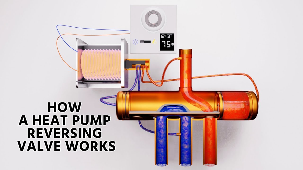
How a Heat Pump Reversing Valve Works - YouTube

Three Way Valve of HVAC System in Urdu/Hindi - YouTube
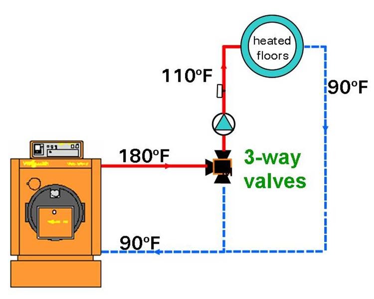
Enhanced Living Blog: Radiant Heating 101: Mixing valves and controls
